In my last blog post I started to show off something I threw together in OpenSCAD in a few minutes, and I have been playing around with the application a bit more since then. So I had a rough idea in my head of some furniture I wanted to build to improve my bedroom, and since I haven’t touched a CAD application in quite a while, doing it in code just makes sense to me.

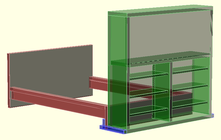
Below you can see my updated code where I have basically made use of variables, modules, and color. Personally, I found it very easy and straight forward to follow, however if anybody reading this is struggling to understand it and is genuinely interested, I would be more than happy to create another blog post in the near future explaining how it all works (essentially a tutorial).

// Bed Variables
BedWidth = 156.7;
FooterHeight = 30;
BedBoardThickness = 5;
ThickerBedBoard = BedBoardThickness + 0.2;
InnerSideBeamHeight = 12.5;
InnerSideBeamThickness = 4.5;
UpperSideBeamWidth = 7.5;
SideBeamLength = 201.2;
HeadBoardHeight = 78;
// Shelf Variables
CabinetDepth = 35;
ThinBoard = 3;
ThickBoard = 5;
ShelfSpacing = 20;
TvAreaHeight = 60;
ShelfTotalHeight = 80;
ShelfWidth = (BedWidth-(ThinBoard*2)-ThickBoard)/2;
SupportHeight = FooterHeight-BedBoardThickness-InnerSideBeamHeight;

module bed_frame() {
        union() {
                translate([0,0,0]) {
                        cube([BedWidth,ThickerBedBoard,FooterHeight]);
                }
                translate([BedWidth-UpperSideBeamWidth,ThickerBedBoard,FooterHeight-BedBoardThickness]) {
                        cube([UpperSideBeamWidth,SideBeamLength,BedBoardThickness]);
                }
                translate([0,ThickerBedBoard,FooterHeight-BedBoardThickness]) {
                        cube([UpperSideBeamWidth,SideBeamLength,BedBoardThickness]);
                }
                translate([UpperSideBeamWidth-InnerSideBeamThickness,ThickerBedBoard,(FooterHeight-BedBoardThickness)/2]) {
                        cube([InnerSideBeamThickness,SideBeamLength,InnerSideBeamHeight]);
                }
                translate([BedWidth-UpperSideBeamWidth,ThickerBedBoard,(FooterHeight-BedBoardThickness)/2]) {
                        cube([InnerSideBeamThickness,SideBeamLength,InnerSideBeamHeight]);
                }
                translate([0,SideBeamLength+BedBoardThickness,0]) {
                        cube([BedWidth,BedBoardThickness,HeadBoardHeight]);
                }
        }
}

module tv_stand_shelf() {
        cube([ShelfWidth,CabinetDepth-(ThinBoard*2),ThinBoard]);
}

module tv_stand_mid_shelf() {
        cube([BedWidth-(ThickBoard*2),CabinetDepth,ThickBoard]);
}

module tv_stand_long_shelf() {
        cube([BedWidth,CabinetDepth,ThickBoard]);
}

module tv_side_panel() {
        cube([ThickBoard,CabinetDepth,ShelfTotalHeight+TvAreaHeight+1]);
}

module tv_stand() {
        union() {
                // Top Board
                translate([0,0,TvAreaHeight+ShelfTotalHeight+(ThinBoard*2)]) {
                        tv_stand_long_shelf();
                }
                // TV Base Board
                translate([ThickBoard,0,ShelfTotalHeight+ThinBoard]) {
                        tv_stand_mid_shelf();
                }
                // Bottom Board
                translate([0,0,0]) {
                        tv_stand_long_shelf();
                }
                // TV Backing
                translate([0,0,ShelfTotalHeight+(ThinBoard*2)]) {
                        cube([BedWidth,ThinBoard,TvAreaHeight]);
                }
                // Foot Board
                translate([0,CabinetDepth-ThinBoard,ThinBoard]) {
                        cube([BedWidth,ThinBoard,ShelfTotalHeight]);
                }
                // Left Panel
                translate([0,0,ThickBoard]) {
                        tv_side_panel();
                }
                // Right Panel
                translate([BedWidth-ThickBoard,0,ThickBoard]) {
                        tv_side_panel();
                }
                // Mid Divider
                translate([(BedWidth-ThickBoard)/2,0,ThickBoard]) {
                        cube([ThickBoard,CabinetDepth-ThinBoard,ShelfTotalHeight]);
                }
                // Left Shelves
                translate([ThinBoard,ThinBoard,ShelfSpacing]) {
                        tv_stand_shelf();
                }
                translate([ThinBoard,ThinBoard,(ShelfSpacing*2)+(ThinBoard)]) {
                        tv_stand_shelf();
                }
                translate([ThinBoard,ThinBoard,(ShelfSpacing*3)+(ThinBoard*2)]) {
                        tv_stand_shelf();
                }
                // Right Shelves
                translate([ShelfWidth+ThickBoard+ThinBoard,ThinBoard,ShelfSpacing]) {
                        tv_stand_shelf();
                }
                translate([ShelfWidth+ThickBoard+ThinBoard,ThinBoard,(ShelfSpacing*2)+(ThinBoard)]) {
                        tv_stand_shelf();
                }
                translate([ShelfWidth+ThickBoard+ThinBoard,ThinBoard,(ShelfSpacing*3)+(ThinBoard*2)]) {
                        tv_stand_shelf();
                }
        }
}

module tv_stand_support() {
        union() {
                translate([ThickBoard,CabinetDepth+ThickerBedBoard,0]) {
                        cube([BedWidth,ThickBoard,SupportHeight]);
                }
                translate([0,0,0]) {
                        cube([ThickBoard,CabinetDepth+ThickerBedBoard+ThickBoard,ThickBoard]);
                }
                translate([BedWidth+ThickBoard,0,0]) {
                        cube([ThickBoard,CabinetDepth+ThickerBedBoard+ThickBoard,ThickBoard]);
                }
        }
}

translate([5,35,0]) {
        color("Brown", 0.6) {
                bed_frame();
        }
}
translate([5,0,0]) {
        color("Green", 0.4) {
                tv_stand();
        }
}
translate([0,0,0]) {
        color("Blue", 0.4) {
                tv_stand_support();
        }
}

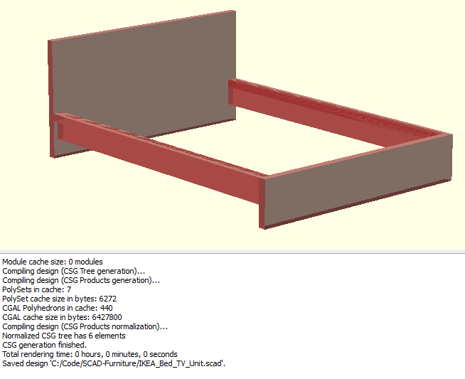
Once again, here is what the code has generated for me.

001

I have not really had a chance to start blogging anything recently as I have been too busy with Christmas, New Year and being back at work (with a lot of things going on). I am planning on posting up some more blog posts around a load of JavaScript I have been working on, and once things settle a bit more, I will do some more electronics posts!

Today I am going to be going over a project I have taken on. When I was a kid I used to spend my school holidays at the furniture factory that my dad owned back in South Africa and always enjoyed making things there. As an adult, I still love making things, but rarely build something out of wood with the exception of what I buy from IKEA. So anyway, I have decided that I want to build a small unit that will attach to the end of my bed, which will be a basic TV cabinet. I knew exactly how I want it to look, how high off of the actual bed it should be so that my feet never touch the screen, and that I do not want it to be possible to get knocked over if I toss and turn from one bad night’s rest. I tried looking around for something that was roughly what I wanted, and I found nothing! So I have taken it upon myself to build what I want, and I thought that perhaps I could take it as an opportunity to also make some additional storage space for my bedroom. If it turns out to not be too expensive, then I will also build a couple of really nice bedside cabinets with built in Qi wireless charging and improved bedside lighting for reading in bed.

So after a bit of thought, I wasn’t sure how best to design this other than on a bit of paper. I used to be really good with 3D Studio Max, but unfortunately stopped using it a good few years ago (at least 10) and everything else out isn’t all that simple to throw something together in my opinion. It then struck me… a friend told me about an application called OpenSCAD, where you write simple code and it draws objects in 3D space. I thought I would give it a quick try, and it seems to do the job perfectly! Here’s the code used to make my IKEA bed frame into a 3D model…

module bed_frame() {
	union() {
		translate([0,0,0]) {
			cube([156.7,5.2,30]);
		}
		translate([149.2,5.2,25]) {
			cube([7.5,201,5]);
		}
		translate([0,5.2,25]) {
			cube([7.5,201,5]);
		}
		translate([3,5.2,12.5]) {
			cube([4.5,201,17.5]);
		}
		translate([149.2,5.2,12.5]){
			cube([4.5,201,17.5]);
		}
		translate([0,206.2,0]) {
			cube([156.7,5,78]);
		}
	}
}

translate([0,0,0]) {
	color("Brown", 0.6) {
		bed_frame();
	}
}

…and here is what that code makes

001

So I think it is clear to say that I will will designing the actual cabinet and everything else with OpenSCAD!

Today I was in Poundland just generally looking around for some toys for my mother’s dog, as after visiting for Christmas I noticed he had destroyed all of his toys and needed some new ones. While I was in the store, I noticed they were selling a Solar powered garden lantern, which states that that it automatically turns on at dusk. For £1, I couldn’t resist taking one home to break apart and have a look inside.

So here it is in all it’s cheap glory.

001

On the top you can clearly see a nice 5cm x 5cm solar panel.

002

You can very easily screw off the top, as that reveals switch to turn it on and off and you can also clearly see the LED.

003 004

With very little persuasion at all, the big round thing in the middle (seen above) just comes right off which exposes everything inside.

005

The next part was a bit trickier as I needed to a pair of plier to carefully remove the circuit from the plastic that was clipped around it.

006

A closer look at the back of the solar panel, and we can see that it’s a TRONY SC3030S-4NA, which after a quick search online, tells us that it’s a 10mA at 2.5v all glass circuit.

007

Looking at the circuit board we have the following:

  • 220Ω resistor
  • Diode
  • Slider switch
  • LED
  • Black Blob (unknown iC)
  • 2.5v/10mA Solar Cell
  • 1.2v/40mAh Ni-MH Battery

008 009 010

The circuit is simple to work out, but unfortunately because it’s a cheap device the iC is just a black blob which we can never determine what it actually is. Putting that aside, we have a solar cell which charges a battery, and a diode to prevent battery power going back to the solar cell when it’s not charging. The LED turns on when the battery isn’t charging, with the power that comes back from the battery. With that all in mind, we have a very small circuit that can be used for a number of other projects. We can remove the LED and place something else in it’s stead which takes 1.2v, or even chain multiple LEDs up to it, but keeping in mind that the more that draws from it, the shorter life we will get from the battery. You can potentially replace the battery for a bigger Ni-MH cell to give it a longer battery life, but also need to keep in mind that the charge rate will still be quite slow due to the restrictions of the solar cell, and I am not sure if the black blob applies any further restrictions. You can also potentially remove the switch, and just bridge the connection so that it’s always on, or hook it up to something else you prefer.

A little over a year ago, I treated myself to a nice gaming headset. I did a little bit of research and found a pair that were all that I could ever want and their sound was apparently really good (as far as reviews went), with a bonus that I am able to apply voice filters. So I purchased a Turtle Beach XP500 wireless headset, and absolutely loved them, and still do today. They are extremely comfortable, the sound you get out of them is absolutely amazing, and the voicer filters are great for annoying my friends online Xbox Live. The only problem I have with them is that they require two AA batteries, and although I generally always have some rechargeable batteries kicking around, I do not always remember to charge them! So a project I am going to undertake in the new year is to improve these headphones so that I no longer require batteries.

So basically what I am thinking is to remove the batteries and their cover, create a simple circuit that connects to a Lithium Ion battery, provides a USB socket and for it to fit snugly in the headphones. Ultimately, it will allow me to use them with the new batteries when they are charged, and when they are running low on power, I can simply hook a USB cable into them, and they can charge AND continue to work at the same time.

Here is a video of what I am planning on “upgrading” :

Just as the title says, it’s really a risk business. Granted that I have only been making (to sell) my own kits for a very short period of time, I have learned a lot in a short period of time. It all comes down to risk. The first kits I made were the “Soldering is Easy” flower badges that I made for Brighton Mini Maker Faire 2013. I saw the design of the badge from 2012 (as I was one of the helpers on the stand in 2012), and really thought it was a bit too plain and boring for kids. So having volunteered to run the stand this year, I decided to take it upon myself to make a new design, something that was still quick and simple to put together, but also something that resembled something. I was playing around with ideas for a couple of weeks before I finally settled on the flower badge design. So I fired up Eagle and slowly turned my idea into a circuit, and equally asking my friend Adam Brunette to check my design as I had never used Eagle before (normally I would use ExpressPCB).

Eventually, my design is finished and I was ready to place an order for both the components and the PCBs to be manufactured professionally, but the big questioned dawned on me… how many should I have made? Well this is where the whole idea of risk came into play, as I am no big business, so really I cannot afford to sink a lot of money into something and potentially get zero return, but again, I need to order a sizable number if I want to keep cost down, as the more you order the cheaper it is. I decided to do a bit of math, and said to myself that the year before, around 180 kits were sold through-out the entire day, so I should order at least that many. The components I needed for the kits were nothing special, there was no iC (microchips) or anything else that I could not use for any other project of mine, so ordering those in bulk is no problem at all. So it was just down to the circuit boards. Worst case scenario, I buy a load, nobody likes them and I am stuck with a load of boards that nobody likes, and am out of pocket. I decided to take a risk and buy 300, sell them at cost (making them a third of the price of the year before), and see what happens.

Well, on the day I had my kits and was setting up my stand with a horrible feeling of dread in my stomach, and constant worrying “what if nobody likes my design?”, “what if some of them are faulty?”, and a number of other “what if…“‘s. So as a number of people who know me, or were at that Maker Faire, they know that not only were my kits popular, but I managed to sell all 300 of them within the space of 4 hours, and had a number of people still wanting more!

So Christmas time has come by, and I decided to try running a Christmas workshop at Build Brighton where people would be able to build some electronic kits with a Christmas theme. I had an idea of a PCB I wanted to make the year before, which was a Christmas tree made from two boards interconnecting, however previously I was looking at etching them myself, along with painting them green (or at least covering them in something green). I never went through the idea in 2012, as it seemed like a lot of effort for something that might not turn out too well. However, this time around I had already gained experience in having PCBs manufactured professionally, so I would go with that option again. Once again, I came up with a design and checked with my friend Adam for confirmation that what I had would work. I also made some badges, but made them into snow men as to be more festive.

Once again, I came into the situation of “how many do I have made?”. Well again I tried to use some logic and thought that although I had sold out of all 300 in a single day at Maker Faire, that was Maker Faire and that it had a lot of good advertising and a lot of people attending. The Christmas faire I was planning to hold at Build Brighton would not be advertised half as well, so although it’s over 4 weeks, it would be unlikely to receive as many visitors. So I randomly said in my head that I would make 100 trees and 100 snow men. At first the sales were quite slow, but after a couple weeks, the few people that had bought them had shown them to their friends and co-workers, which resulted in an ensuing increase of sales. Not only did people just like the trees, but it seemed that everybody wanted one. They were fun to build, as there are two PCBs which slot together, and it’s relatively simple to put them together. One friend showed them to her office, and everybody wanted them as desk ornaments, or for weekend project’s for them to do with their kids. So I am coming up to my final workshop (4 of 4), and unfortunately only have 6 tree kits left, and I have sold more than half of my snow-men badges. I have made back my investment already, and every sale at the moment is profit.

I worried about not selling enough to make back my investment, but in fact have once again simply not made enough. With that said, as with any project, I have received some great feedback which I will use to improve the kits for next year.

So I suppose I will conclude that although it is risky to make your own electronics to try and sell as kits, if you put in enough effort for them to look good, regardless of how simple they are, people are going to buy them. The more complex your kit is, the smaller audience you’re able to attract. Simple blinking LEDs have won in both of my attempts at making kits to sell for an event with great success. I am now working on a number of other kit ideas, and will most likely again question how many to make. I have been successful twice, but perhaps that was just luck? Who knows, but I’ll just pan it out carefully and see how it goes!