Tree-Kit-Trinket - Tutorial without switch
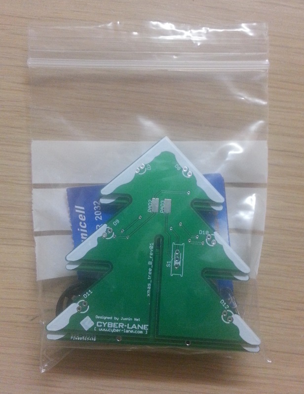
Step 1 - Your kit
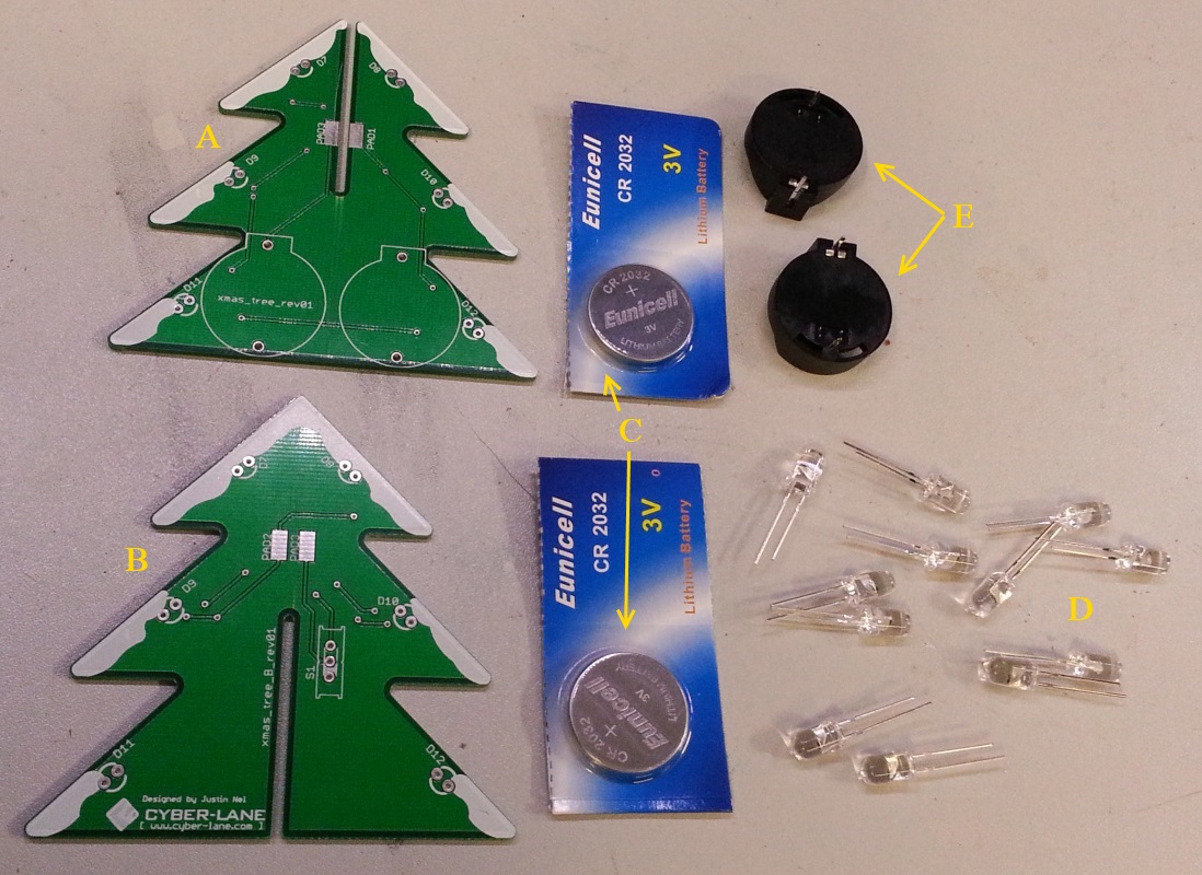
–row– You should have a kit which looks similar to this –column– Each kit comes with the following pieces:
A) Tree circuit 1 - this is the board which will have the battery holders attached.
B) Tree circuit 2 - this is the second board which helps the first tree stand up
C) 2x CR2032 coincell batteries
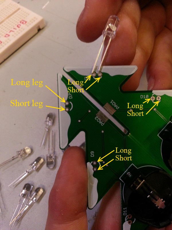
D) 12x LEDs (these will be the lights on the tree) - one leg is longer than the other: the longer leg goes into the top most hole with writing next to it, and the shorter leg in the other.
E) 2x battery holders
–row–
 –column–
 –row–
–row–
Step 2 - The battery holders
–row–
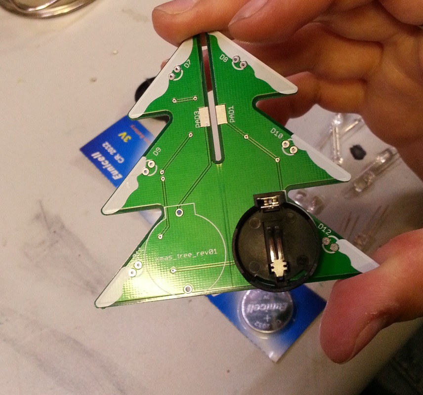
You begin by placing the battery holders into the holes on Tree circuit 1. Please take note to the shape of battery holder and the outline.
–column–
Ensure that you place the square edge of the battery holder to the top where the outline matches.
–row–
 –column–
 –row–
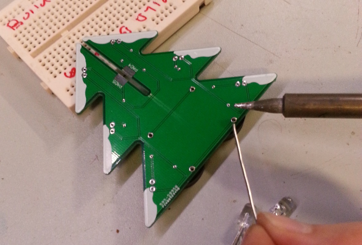
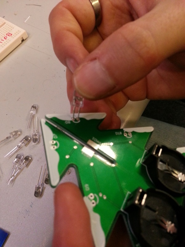
Carefully turn the board over, and make use of a pencil or something of similar height to rest the the top of the tree on, so you are able to solder the battery holders on without them wobbling.
–row–
Carefully turn the board over, and make use of a pencil or something of similar height to rest the the top of the tree on, so you are able to solder the battery holders on without them wobbling.
For detailed instructions on how to solder, please visit this link (coming soon).
–column–
 –row–
–row–
Step 3 - The lights on the tree
–row–
As mentioned earlier on, the LEDs have one leg longer than the other. The longer leg goes into the top most hole as shown in the following picture.
–row–
 –column–
 –row–
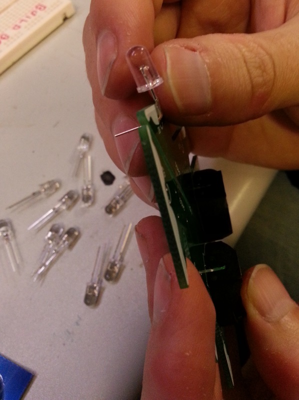
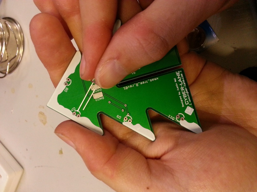
When pushing the LEDs through the holes, make sure not not push them all the way through. Once they are about half way through, bend them towards the edge of the board until they are flush against the board.
–column–
When bent, the LEDs should look similar to this:
–row–
–row–
When pushing the LEDs through the holes, make sure not not push them all the way through. Once they are about half way through, bend them towards the edge of the board until they are flush against the board.
–column–
When bent, the LEDs should look similar to this:
–row–
 –column–
 –row–
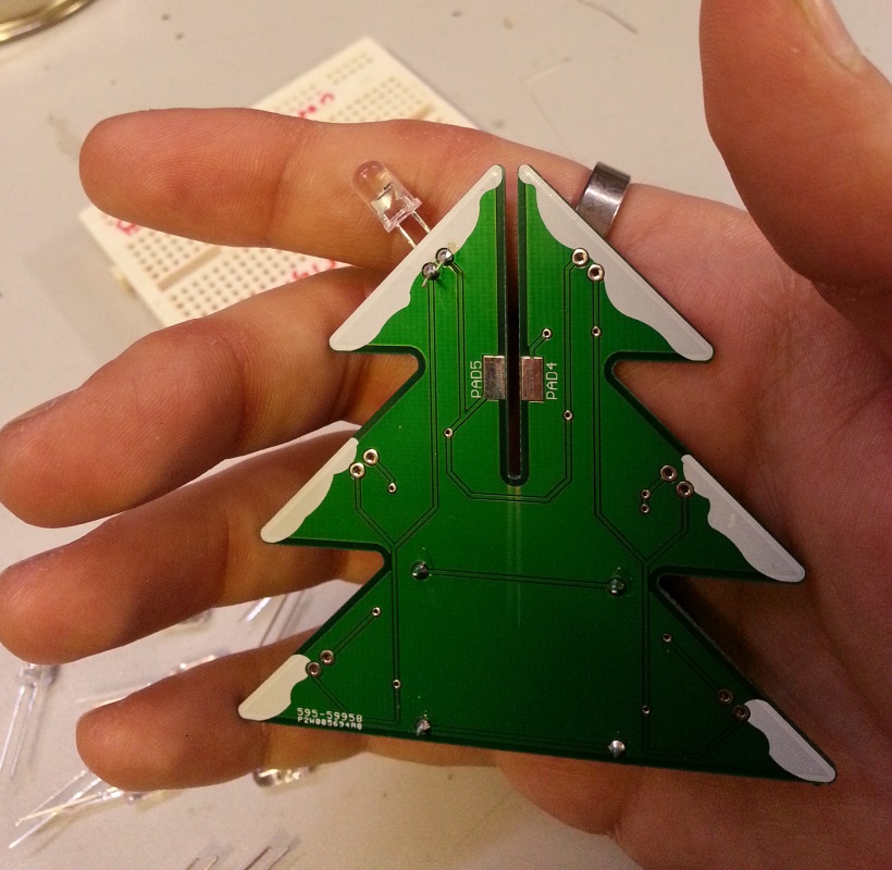
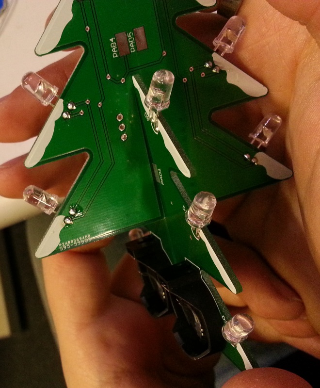
Once you have all of the LEDs in place and the legs all bent, it should look much like this:
–column–
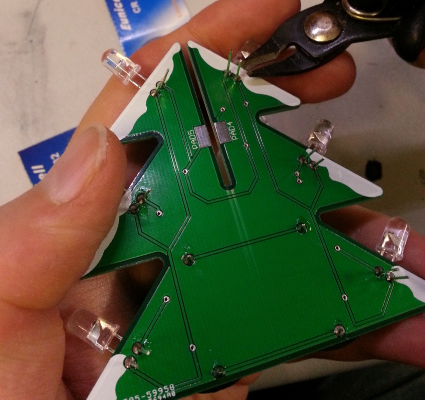
Solder all of the legs into place, and then you can begin to trim them down with some wire cutters.
–row–
–row–
Once you have all of the LEDs in place and the legs all bent, it should look much like this:
–column–
Solder all of the legs into place, and then you can begin to trim them down with some wire cutters.
–row–
 –column–
 –row–
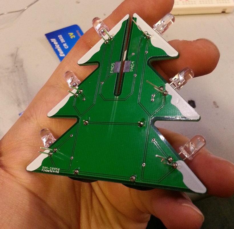
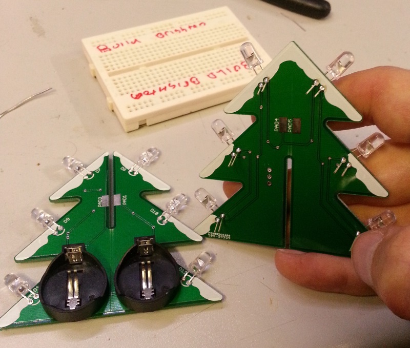
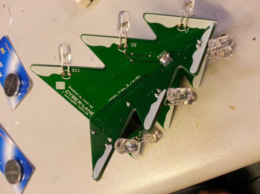
Once you complete circuit 1, you can move onto circuit 2. Repeat all the previous steps from the beginning of Step 3
–column–
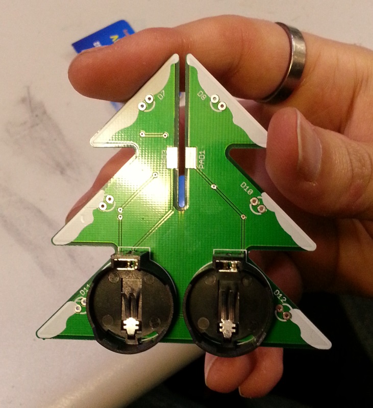
After you have all the LEDs in place on circuit 2, the two boards should look much like this:
–row–
–row–
Once you complete circuit 1, you can move onto circuit 2. Repeat all the previous steps from the beginning of Step 3
–column–
After you have all the LEDs in place on circuit 2, the two boards should look much like this:
–row–
 –column–
 –row–
–row–
Step 4 - Connecting the two boards
–row–
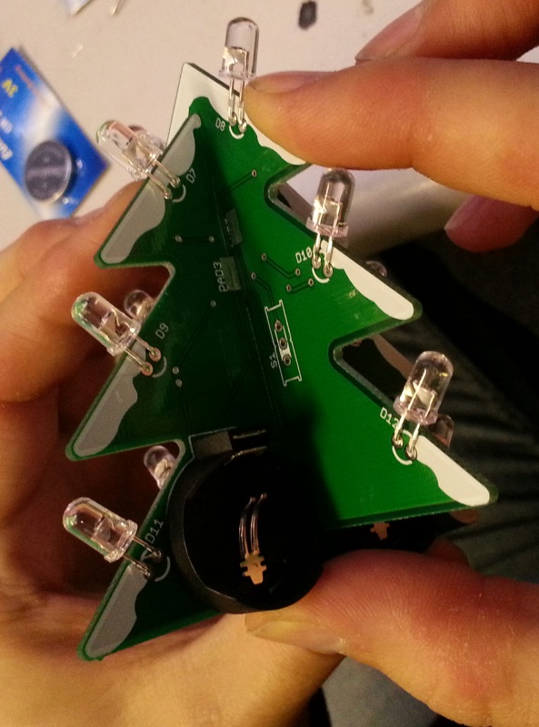
Push the two boards together as seen in the image below:
–column–
It is quite a snug fit, so might seem a bit tight. Don’t worry though, it does fit!
–row–
 –column–
 –row–
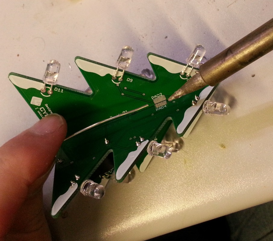
Now we need to solder the tree together. On each of the four sides, there are some silver pads which need to be soldered together. To do this, you need to use the soldering iron to apply a big lump of solder onto each of the two sides. Once you have a nice big lump on each side, you can use the soldering iron to connect the two lumps.
–column–
Once the pads are connected, it will look like this:
–row–
–row–
Now we need to solder the tree together. On each of the four sides, there are some silver pads which need to be soldered together. To do this, you need to use the soldering iron to apply a big lump of solder onto each of the two sides. Once you have a nice big lump on each side, you can use the soldering iron to connect the two lumps.
–column–
Once the pads are connected, it will look like this:
–row–
 –column–
 –row–
–row–
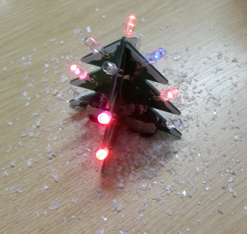
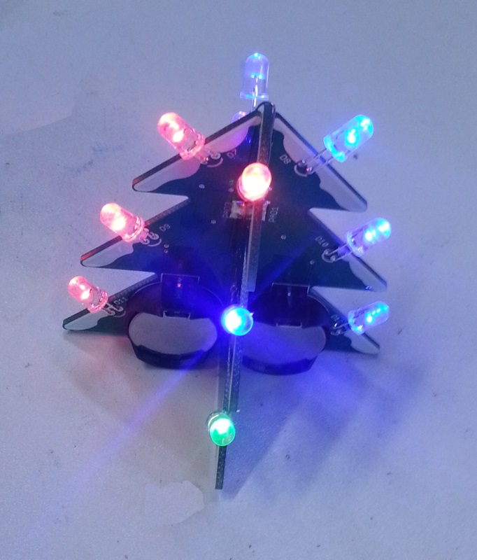
Step 5 - The finished product
–row–
Just connect the batteries, positive side up (the side with the writing). To remove the battery, you need some nails or needle nose pliers, and you need only pinch the square side of the battery holder to release the battery.
–row–
 –column–